

EN
In precision manufacturing, injection molding is widely regarded as the "mother of industry." Yet many quality defects—such as flash, sink marks, and short shots—often trace back not to process parameters, but to an overlooked root cause: improper machine selection at the very outset. A poorly chosen machine undermines even the best mold design. This article breaks down the three core principles of machine selection: fit, fill, and clamp.
Fit: Spatial Compatibility Between Mold and Clamping System
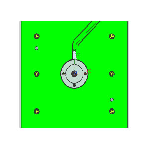
The first and most fundamental requirement is ensuring the mold can be physically accommodated within the clamping system. Several dimensional factors must be evaluated:
Tie-bar spacing: The mold width must be smaller than the horizontal distance between the tie bars; otherwise, installation is impossible. Vertically, while the mold height may slightly exceed the tie-bar spacing, it must never surpass the actual platen dimension—otherwise, clamping force cannot be uniformly transmitted.
Mold thickness: Every injection molding machine has a minimum and maximum mold thickness limit. The closed mold height must fall within this range. Too thin, and the mold cannot be clamped; too thick, and it simply will not fit.
Clamping stroke: The opening stroke must be sufficiently large—typically a multiple of the part height—to allow for smooth part ejection and to accommodate robotic handling equipment.
Recommendation: Mold design and machine parameters should be aligned from the outset. It is advisable to keep the mold's external dimensions moderately smaller than the tie-bar spacing to allow flexibility for future mold changes and fine-tuning.
Fill: Balancing Shot Capacity and Melt Quality
"Filling the cavity" is not merely about reaching the far end of the mold—it must be achieved under optimal plastication conditions. This directly affects the mechanical properties and surface quality of the finished part.
Shot weight verification: The theoretical maximum injection capacity must exceed the combined weight of the part and the runner system.
Safety margin: To ensure shot-to-shot consistency, the total shot weight is typically kept at a defined percentage of the machine's maximum theoretical shot capacity. This practice keeps the screw stroke within a reasonable range, preventing uneven plastication or thermal degradation of the resin.
Special consideration for crystalline materials: For engineering resins such as polyamide and polyoxymethylene, which require higher thermal input for homogeneous melting, this percentage must be maintained at a more conservative level. This ensures stable crystallinity and controlled shrinkage, which are critical for dimensional accuracy.
Clamp: Counteracting Cavity Pressure with Sufficient Force
This is the most technically demanding aspect of the selection process. Insufficient clamping force leads to mold parting and flash, while excessive force may deform the mold and waste energy.
Fundamental formula: Required clamping force is the product of the projected part area and the cavity pressure.
The real challenge lies in determining cavity pressure. One can visualize it as the force of water seeping through and compacting soil in a flowerpot. This pressure is influenced by a range of factors:
Gate location and count: Gate placement and number determine the melt flow path. Multiple gates effectively reduce the flow-length ratio and lower cavity pressure, whereas a single gate demands higher pressure to drive flow over longer distances.
Gate dimensions: An undersized gate creates a bottleneck, resulting in substantial pressure loss. An oversized gate facilitates pressure transmission but delays freeze-off, extending the cycle time.
Wall thickness and flow length: Thinner walls generate higher resistance, while longer flow paths cause greater pressure decay at the extremities.
Material viscosity: Engineering plastics such as polycarbonate are far more viscous than commodity resins like polypropylene, requiring significantly higher injection pressure.
Injection speed: Higher speeds can improve flowability through shear-thinning, but they also cause a sharp rise in peak pressure at the flow front.
Strategy: For standard commodity plastics, clamping force is often estimated using empirical constants. For high-precision or geometrically complex parts, we strongly recommend using advanced mold-flow simulation software to precisely determine the required force, with an ample safety margin incorporated.
Systematic Selection and Future-Proofing
Beyond the three core principles, machine selection must also account for screw design (commodity, engineering, or specialty polymers), drive technology (hydraulic, all-electric, or servo-hydraulic), and specialized processes (two-shot, high-speed, or micro-precision molding).
Our standard workflow:
Data collection: Thoroughly analyze part drawings, wall thickness distribution, material datasheets, and mold construction.
Parameter calculation: Apply the established formulas to generate a shortlist of candidate machines.
Process validation: For specialty materials, verify the screw compression ratio and length-to-diameter ratio to ensure adequate plastication.
Redundancy planning: Build a reasonable margin into every critical parameter—clamping force, shot capacity, and stroke—to accommodate future mold modifications or increased production volumes.
Closing Thoughts
Selecting the right injection molding machine is a systematic exercise in balancing spatial geometry, fluid dynamics, and materials science. A well-executed selection directly translates into lower energy consumption, higher yield rates, and extended mold life. We are committed to providing tailored technical support that mitigates production risks from the very beginning.
